


0 : Odsłon:
The Invention of Hans Coler, Relating to an Alleged New Source of Power.
I. Object of Visit & Summary ~
Coler is the inventor of two devices by which it is alleged electrical energy may be derived without a chemical or mechanical source of power. Since an official interest was taken in his inventions by the German Admiralty it was felt that an investigation was warranted, although normally it would be considered that such a claim could only be fraudulent.
Accordingly Coler was visited and interrogated. He proved to be cooperative and willing to disclose all details of his devices, and consented to build up and put into operation a small model of the so-called "Magnetstromapparat" [Magnet Power Apparatus] using material supplied to him by us, and working only in our presence. With this device, consisting only of permanent magnets, copper coils, and condensers in a static arrangement he showed that he could obtain a tension of 450 millivolts for a period of some hours; and in a repetition of the experiment the next day 60 millivolts was recorded for a short period. The apparatus has been brought back and is now being further investigated.
Coler also discussed another device called the "Stromzeuger", from which he claimed that with an input of a few watts from a dry battery an output of 6 kilowatts could be obtained indefinitely. No example of this apparatus exists today, but Coler expressed his willingness to construct it, given the materials, the time required being about three weeks.
Opportunity was taken to interrogate Dr. F. Modersohn who had been associated with Coler for ten years and had provided financial backing. He corroborated Coler’s story in every detail.
Neither Coler nor Modersohn were able to give any theory to account for the working of these devices, using acceptable scientific notions.
II. Historical Notes ~
1. The "Magnetstromapparat"
This device consists of six permanent magnets wound in a special way so that the circuit includes the magnet itself as well as the winding (See Figure 1). These six magnet-coils are arranged in a hexagon and connected as shown in the diagram (Figures 2 & 3), in a circuit which includes two small condensers, a switch, and a pair of solenoidal coils, one sliding inside the other. To bring the device into operation, the switch is left open, the magnets are moved slightly apart, and the sliding coil set into various positions, with a wait of several minutes between adjustments. The magnets are then separated still further, and the coils moved again. This process is repeated until at a critical separation of the magnets an indication appears on the voltmeter. The switch is now closed, and the procedure continued more slowly. The tension then builds up gradually to a maximum, and should then remain indefinitely. The greatest tension obtained was stated to be 12 volts.
The "Magnetstromapparat" was developed by Coler and von Unruh (now dead) early in 1933, and they were later assisted by Franz Haid of Siemens-Schukert, who built himself a model which worked in December 1933. This was seen by Dr. Kurt Mie of Berlin Technische Hochschule and Herr Fehr (Haber’s assistant at the K.W.I.) who reported that the device apparently worked, and they could detect no fraud. One model is said to have worked for 3 months locked in a room in the Norwegian Legation in Berlin in 1933. No further work appears to have been done on this system since that date.
2. The "Stromzeuger"
This device consists of an arrangement of magnets, flat coils, and copper plates, with a primary circuit energized by a small dry battery. The output from the secondary was used to light a bank of lamps and was claimed to be many time the original input, and to continue indefinitely. Details of this circuit, and a theory as to its mode of operation were given (summarized in Appendix I).
In 1925 Coler showed a small (10 watt) version to Prof. Kloss (Berlin), who asked the Government to give it a thorough investigation, but this was refused, as was also a patent, on the grounds that it was a "perpetual motion machine". This version was also seen by Profs. Schumann (Munich) Bragatad (Trondheim) and Knudsen (Copenhagen). Reports by Kloss and Schumann are translated in Appendices II and III.
In 1933 Coler and von Unruh made up a slightly larger model with an output of 70 watts. This was demonstrated to Dr. F. Modersohn, who obtained from Schumann and Kloss confirmation of their tests in 1926. Modersohn then consented to back the invention, and formed a company (Coler g.m.b.h.) to continue the development. At the same time a Norwegian group had been giving financial support to Coler, and these two groups clashed. Modersohn’s connection with Rheinmetall Borsig, and hence with the official Hermann Goering combine gave him an advantage in this. Coler then in 1937 built for the Company a larger version with an output of 6 kilowatts.
In 1943 Modersohn brought the device to the attention of the Research Department of the O.K.M. The investigation was placed under the direction of the Oberaurat Seysen, who sent Dr. H. Frohlich to work with Coler from 1.4.43 to 25.9.43. Frohlich was convinced of the reality of the phenomenon, and set about investigating the fundamentals of the device. He apparently concentrated on a study of the energy changes which occur on the opening and closing of the inductive circuits. At the end of the period he was transferred to B.M.W. to work on aerodynamic problems and is now working in Moscow.
In 1944 a contract was arranged with the O.K.W. with Continental Metall A.G. for further development, but this was never carried out owing to the state of the country. In 1945 the apparatus was destroyed by a bomb, in Kohlberg, whither Coler had evacuated. Since at that time Coler had been employed, sometimes as an engineer, sometimes as a laborer. Modersohn had severed his connection with Rheinmetall Borsig, of which he had been a director, and was working for the Russian authorities as a consultant in chemical engineering.
III. Report ~
1. Interrogation of Coler ~
Coler was questioned first about the history of his invnetions, when the details above were given.
He was then questioned about the theory of the devices, but he was unable to give any coherent suggestions as to the mechanism. He sated that his researches (apparently conducted with crude apparatus) into the nature of magnetism had lead him to conclude that ferro-magnetism was an oscillating phenomenon, of frequency about 180 kilohertz. This oscillation took place in the magnetic circuit of the apparatus, and induced in the electrical circuit oscillations the frequency which of course depended on the values of the components used. These two phenomena interacted, and gradually built up the tension. As the mechanism was not understood the proper arrangement could not be worked out, but had to be arrived at by experiment, and the apparatus had to be brought into adjustment by similar trial and error methods. Coler stated that the strength of the magnets did not decrease during the use of the apparatus; and suggested that he was tapping a new sort of energy hitherto unknown "Raumenergie" (Space-energy). Coler gave a resume of the work done by Dr. Frohlich for the O.K.W., and produced a copy of Frohlich’s report, written jointly with himself (translation reproduced in Appendix IV) and a report of his own (part of which is given in Appendix V).
Coler was asked if he would consent to build models of these devices if material was made available. He agreed that he could do this, and stated that it would take one week to construct a "Magnetstromapparat", and a month to construct a "Stromzeuger". Accordingly we supplied the magnets, condensers and copper wire needed for the former, and Coler proceeded to build an apparatus as discussed in Section 3. A list of materials required for the "Stromzeuger" was drawn up by Coler.
2. Interrogation of Dr. F. Modersohn
Modersohn was questioned about the history of these devices, with which he had been concerned financially, and corroborated the details given by Coler. He stated that he had at first disbelieved Coler claims but had taken great precautions to eliminate fraud. He had seen the 70 watt "Stromzeuger" working on a number of occasions, and had taken it while working from one room to another. All parts were visible and nothing was hidden. As he was himself not expert he had tried to get experts to examine it thoroughly, but reputable scientists either refused to have anything to do with it at all, or else were more concerned to find a fraud than to see how it worked. The exception was Dr. Frohlich, who was convinced of the reality of the effect, and who also believed that the secret was to be found in the special inductive circuit used. He had made experiments to test his ideas, but Modersohn denied knowledge of the results. Modersohn was extremely methodical, and showed his files on the subject: these contained copies of all letters and reports concerning the device, since 1933.
3. Construction & Testing of the "Magnetstromapparat"
In our presence and with material supplied by us (some brought from England and the rest bought locally) Coler built an apparatus as shown in Figures 1, 2, and 3. It is to be noted that some magnets are wound in a clockwise direction looking at the N pole (called left) and others in an anti-clockwise direction (called right). The magnets were selected to be as nearly equal in strength as possible, and the resistance of the magnet-coil combination was checked after winding to see that this also was uniform (about 0.33 ohm). The physical arrangement was as shown in Figure 2, in a breadboard style. Measurements of voltage and current across A-B were made with a Mavometer. A mechanical arrangement of sliders and cranks for separating the magnets evenly all round was made up.
On 1.7.46 experiments were being continued after three days of fruitless adjusting, and when the magnets were at a separation of about 7 mm., the first small deflection was noted (about 9 a.m.). The switch was closed and by slow adjustment of the sliding coil, and by increasing the separation of the magnets to just over 8 mm., by 11 a.m. the tension was raised to 250 millivolts and by 12.30 p.m. it was 450 millivolts. This was maintained for another 3 hours when a soldered tag became disconnected, and the meter slowly dropped back to zero. Soldering up the broken connection did not restore the tension. The magnets were closed up and left overnight and the same procedure for finding the adjustment was repeated on 7.24.46. After about three hours a deflection of 60 millivolts was obtained; this was maintained for more than 30 minutes, but then decreased to zero when further adjustments were tried.
During all this work the model was completely open, and nothing could be hidden in it. The breadboard and meter could be picked up and moved round the room, tilted, or turned, without effect.
The apparatus would appear to be too crude to act as a receiver of broadcast energy, or to operate by induction from the mains (the nearest cable being at least 6 feet away), and the result for the moment must be regarded as inexplicable.
IV. Conclusions ~
1. It was judged that Coler was an honest experimenter and not a fraud, and due respect must be paid to the judgment of Frohlich in the matter as deduced from his report to Seysen.
2. The result obtained was genuine in so far as could be tested with the facilities available, but no attempt has yet been made to find an explanation for the phenomenon.
3. It is felt that further investigation by an expert in electromagnetic theory is warranted, and that Coler’s offer to construct a model of the "Stromzeuger" should be taken up.
Appendix I ~ Summary Account of the "Stromzeuger"
1. The basic principle is that an electron is to be regarded not only as a negatively charged particle but also as a South magnetic pole.
The basic element is that of an open secondary circuit, capacity loaded, inductively coupled to a primary circuit. The novel feature is that the capacities are connected to the secondary core through permanent magnets, as shown:
It is claimed that, on switching on the primary circuit, "separation of charges" takes place, i.e., Magnet 1 becomes positively charged and Magnet 2 becomes negatively charged, and that these charges are "magnetically polarized" when they are formed, owing to the presence of the magnets. On switching off the primary circuit a "reversing current" flows in the secondary, but the magnets "do not exert a polarizing effect on this reversal".
2. Two of these basic elements are now placed together making a double system or stage with the plates close together in parallel planes as shown:
The secondary windings are both exactly equal and wound in a direction such that on switching on the primary coil the electrons in the secondary coil flow from P1 to P2 [P = Plate] and F1 to F2 [F = "Flat Spool"].
It is then stated that system merely has an inducing effect, and the useful current comes into existence in the system.
3. A single stage cannot be effective but two stages connected so that the numbers of effective North and South poles are equal will provide a basic working arrangement. More double stages can then be added to provide higher outputs.
4. It is then stated that as well as the normal electrons flowing from the battery and from induction when the circuit is opened or closed, "space electron" flow from "repelling spaces" to "attracting spaces" between the plates, but this theory I was unable to follow any further.
Appendix II ~ Translation of Report by Professor M. Kloss (Berlin) on Tests on the Apparatus, constructed by Captain Coler (dated 4 March 1926)
On the 3rd of March I have on request inspected the apparatus constructed by Captain Coler, and I undertook some tests regarding its efficiency. Professor Dr. R. Franke from the Technical College of Berlin was present at these tests.
The apparatus, in its construction already known to me from a previous inspection, consists of:
a double row system of copper plates,
a double-row system of flat spools,
and a system of electromagnets,
to whose cores silver wires are attached and through which branch currents of the plate-system are conducted. For each of the three systems a 3-part accumulator battery of 6 volts/6.5 ampere-hours capacity is provided. The plate-circuit and the spool circuit are parallel so that the two batteries appertaining thereto can also be replaced by a single battery. This was ascertained towards the end of the tests by switching off the one battery while the apparatus was working.
When asked why two batteries were used at all, Capt. Coler declared that for starting the apparatus a double battery is necessary to get a second charge-impetus after exciting with the one battery, and this for releasing the peculiar character of the apparatus. A test made towards the finish of a series of trials confirmed this assertion in as much as the mechanism could not be started with the single battery; on the contrary, the "adjustment" of the mechanism got disturbed.
Current-indicators are built into each of the three circuits mentioned, as well as volt-meters, behind some switch resistances necessary for the "adjustment". Between the open ends of the two plate and spool-systems there are the terminal clamps for the effective circuit for whose loading 3 bulbs of 8 volts are provided. The apparatus was then put into action and above all the load was tested with the aid of the built-in instruments, that is on being loaded with 2 lamps, 3 lamps and running light. Thereupon and by means of precision-instrument (continuous-current type) Siemens & Halske Nr. 423820 the indications of the built-in instruments were controlled by switching on the mentioned precision-instrument in turn to the single circuits, that is direct to the one terminal clamp of the battery, in order to ascertain if perhaps through any by-connections with the batteries, not conspicuous at once, more current might be received than the built-in instruments were showing. The tests showed a sufficient conformity within the bounds of measuring accuracy.
Finally the same instrument was switched on also to the effect circuit, whereby some greater differences with the instruments built into this circuit were shown; on the other hand, however, not such differences as to alter fundamentally the total result in any way.
In order to find out besides, whether the output current might be identical with a wave-current overlapping continuous current, the last control test was repeated by using a hotwire instrument furnished by me, make of Hartmann & Braun, Nr. 254159. In case there would have been such wave-currents, the hotwire instrument would have had to indicate a bigger current than was shown by the continuous-current instrument. In reality, however, a somewhat smaller current was found was when employing the hotwire instrument. This may be explained by the fact that the inner resistance of the instrument is about 10 times greater than that of the continuous-current instrument, so that when switching on the hotwire instrument the load of the apparatus was somewhat lessened. The difference between 3.08 ampere measured with the continuous-current instrument as compared with 2.95 ampere measured with the hotwire-instrument is easily explained when taking into account the divergences of the two instrument resistances. Therefore one can infer from this test that in the load-circuit we have to deal with real continuous current.
The results of the tests are compiled in the annexed table.
The figures show very well that the consumption of energy in the external circuit is greater than the energy taken from the batteries. According to the circuit, produced by Captain Coler, which within this short time I could not check in all its parts, the magnet-exciting circuit is fed by a special battery, completely separated from the other two circuits. Consequently, a direct comparison of efficiency and consumption of the apparatus would mean that only the sum of current of the plate circuit and of the spool circuit would count. After the established estimates with my own instrument and on a load of 3 bulbs, there was resulting a current from the two mentioned batteries of 0.215 + 0.070 = 0.285 ampere. At the same time the three bulbs consumed ca. 3.7 ampere, according to the built-in instruments, which is about 0.2 ampere too much as was proved later on by a control of this instrument, so that the real consumption has been about 3.5 ampere at a tension of about 2.3 volt.
The reception of current from the two batteries in this case consequently was 1.7 watt while the consumption of the bulbs amounted to about 8 watt. Especially striking in this connection is the considerably higher current-power in the bulb-circuit being about 12 times bigger than the current coming from the two batteries.
We have also absolutely made sure that from the batteries no other conductors led to the apparatus than those into which my instrument was built-in. The fact that an increase of power from the battery to the terminal clamps of the effective circuit in the plate-system takes place, could, indeed, not be tested on the different parts of the apparatus by a direct measuring of the power itself, because Mr. Coler declared that when switching on an instrument in the interior of the system, probably the "adjustment" would be disturbed.
I have therefore tested the decrease of tension in the single plates on a load of three lamps by means of a millivolt-meter, make of Hartmann & Braun, Nr. 462375, in order to get at least in an indirect way an explanation for the increase of current. This examination showed a remarkable increase of tension-losses with a distinct maximum on the third-last plate of the one row. These estimates too are compiled in the table at the end of this judgment.
Results ~ The result of the investigation showed an astonishing working of the apparatus, which, without further researches cannot be explained or compared with the hitherto known characteristics.
Regarding the Cause of the observed characteristics, especially the solution of the question, where the energy in the apparatus originates, no explanation can be given yet, after the short and simple tests.
Solely the conjecture can be expressed that the magnet-system is the source of the energy. It therefore seems desirable to clear this point by further thorough and systematic examinations. For this purpose the proposition of Mr. Coler to construct a bigger apparatus is very sensible, an apparatus, into which from the beginning measuring-instruments should be built in the respective parts of the single circuits in order to enable the "adjustment" of the apparatus including these instruments.
A judgment for the possible utilization of the phenomena, observant in the apparatus, from the economical point of view, I am, of course, not able to pass on after these short tests. This question could only be answered after some lengthened and permanent tests, by which could be established what productiveness the source of energy, existent in the apparatus will show, especially if the magnets, in case they are the supports of the energy-source would wear out after some time, and at what expense each time they could be replaced by new ones.
Above all, however, it appears important that the part or parts of the apparatus, being possibly responsible for causing the observed phenomena, should be taken out in a way as simply as possible and be submitted to an examination in all directions.
Before finishing this, I wish to say that the results of the test are put at the disposal of Captain Coler for which reason I enclose a copy herewith.
I should like to ask, however, the gentlemen in question not to mention my name and that of Professor Franke nor divulge the results of our tests without our express consent, or to make them known publicly and above all not in the press.
Signed,
Dr. Ing. M. Kloss
Professor
Results of Measuring ~ Apparatus Coler (3 March 1926)
Wynalazek Hansa Colera, dotyczący rzekomego nowego źródła mocy.
: Wyślij Wiadomość.
Przetłumacz ten tekst na 91 języków
: Podobne ogłoszenia.

Blat granitowy : Rosetta
: Nazwa: Blaty robocze : Model nr.: : Rodzaj produktu : Granit : Typ: Do samodzielnego montażu : Czas dostawy: 96 h ; Rodzaj powierzchni : Połysk : Materiał : Granit : Kolor: Wiele odmian i wzorów : Waga: Zależna od wymiaru : Grubość : Minimum 2 cm :…
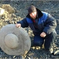
Podczas gdy zespół wcześniej odkrył kilkanaście kamieni w kształcie dysku, ostatnio znalazł szczególnie duży.
Rosyjski serwis informacyjny Bloknot Wołgograd donosi, że odkrycia dysków skamieniałych, dokonała rosyjska grupa ufologiczna i krytozoologiczna Kosmopoisk, znana od 2004 roku jako Ogólnorosyjska. Organizacja Naukowa, kierowana przez Wadima Czernobrowa,…
ROBOT KUCHENNY 1000W KREMOWY
Niezawodny planetarny robot kuchenny o mocy 1000W i dużym zakresie funkcji. Dostawa zawiera miskę ze stali szlachetnej o pojemności 5l i 3-częściowy zestaw mieszadełW razie zaintersowania, prosimy o kontakt. Dane kontaktowe umieszczone sa poniżej lub w…
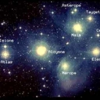
Każdego dnia zbliżamy się do wydarzeń, które przywrócą Ziemię z powrotem do poziomów piątego wymiaru.
Każdego dnia zbliżamy się do wydarzeń, które przywrócą Ziemię z powrotem do poziomów piątego wymiaru. Fale energii nasilają się. Następna fala zawsze będzie energetyczną wibracją większą niż poprzednia. W ten sposób ciała fizyczne dostosowują się bez…
SAMMAR. Producent. Smary, oleje silnikowe.
SAMMAR Sp. z o.o. ma swoją siedzibę na Warmii i Mazurach, w miejscowości Unieszewo położonej 10 km od Olsztyna. Już na początku swojej działalności odnosiliśmy sukcesy, rzucając wyzwania wielkim koncernom naftowym. W 1986 roku otrzymaliśmy jako jedyni w…

60:कपडे शिवणे, संध्याकाळी घालणे, कस्टम मेड आउटफिट्स वाचणे योग्य आहे काय?
कपडे शिवणे, संध्याकाळी घालणे, कस्टम मेड आउटफिट्स वाचणे योग्य आहे काय? जेव्हा एखादा विशेष प्रसंग जवळ येत असतो, उदाहरणार्थ लग्न किंवा मोठा उत्सव, आम्हाला विशेष दिसण्याची इच्छा असते. बर्याचदा या हेतूसाठी आम्हाला नवीन निर्मितीची आवश्यकता असते - आमच्याकडे…

Płytki podłogowe: gres szkliwiony biały
: Nazwa: Płytki podłogowe: : Model nr.: : Typ: nie polerowana : Czas dostawy: 96 h : Pakowanie: Pakiet do 30 kg lub paleta do 200 kg : Waga: 23 kg : Materiał: : Pochodzenie: Polska . Europa : Dostępność: detalicznie. natomiast hurt tylko po umówieniu :…

Looduslikud aroomiteraapia eeterlikud ja aromaatsed õlid.
Looduslikud aroomiteraapia eeterlikud ja aromaatsed õlid. Aroomiteraapia on alternatiivmeditsiini valdkond, mida nimetatakse ka loodusmeditsiiniks ja mis põhineb mitmesuguste lõhnade, aroomide omaduste kasutamisel mitmesuguste vaevuste leevendamiseks.…

Egipcjanie i Grecy mówili, że WODA jest NAJLEPSZA na WSZYSTKO.
Egipcjanie i Grecy mówili, że WODA jest NAJLEPSZA na WSZYSTKO. TAK JEST. Woda źródlana jest najbardziej naturalną formą wody pitnej, czystą i pozbawioną chemii oraz PEŁNĄ ŻYCIOWĄ SIŁĄ ENERGII i minerałów. Dlaczego to ważne? Nasze ciała składają się w…

Verbesserung des Alters: Mitochondrienkrankheit, Proteintransport, Mitochondrien, Altern, neurodegenerative Erkrankungen
Verbesserung des Alters: preisgekrönter Forscher im Kampf gegen Parkinson und Alzheimer: Mitochondrienkrankheit, Proteintransport, Mitochondrien, Altern, neurodegenerative Erkrankungen 20200430AD Ulrike Topf Wir beobachten seit vielen Jahren das Phänomen…
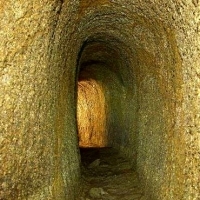
Uwagi dotyczące tajemniczych tuneli
Hinweise zu mysteriösen Tunneln • Der polnische Forscher Jan Pająk behauptet, dass das System alter Tunnel unseren gesamten Planeten einschließlich des Meeresbodens bedeckt. Diese Tunnel sind buchstäblich in den Fels geschmolzen. Ihre Wände sind mit…

דרכי זיהום שפעת וסיבוכים: כיצד להתגונן מפני וירוסים:6
דרכי זיהום שפעת וסיבוכים: כיצד להתגונן מפני וירוסים: נגיף השפעת עצמו מחולק לשלושה סוגים, A, B ו- C, מהם בני האדם נגועים בעיקר בזני A ו- B. הסוג הנפוץ ביותר, תלוי בנוכחות חלבונים ספציפיים על פני הנגיף, מחולק לתתי-סוגים של נוירמיןידאז (N) וההמגלגלוטינין.…

Soksi za wanaume: Nguvu ya miundo na rangi: Faraja juu ya yote:
Soksi za wanaume: Nguvu ya miundo na rangi: Faraja juu ya yote: Mara moja, soksi za wanaume zilibidi zifichwa chini ya suruali au karibu hazionekani. Leo, mtizamo wa sehemu hii ya WARDROBE imebadilika kabisa - wabunifu wanapanda soksi za wanaume wenye…
FILTROPOL. Producent. Masy bitumiczne.
Przedsiębiorstwo FILTROPOL zostało założone w 1991 roku przez Romana Dyżewskiego i Zygmunta Lachowskiego. Od początku działalności firma związana jest z branżą budownictwa drogowego. Pierwsza faza działalności związana była z instalacją systemów…
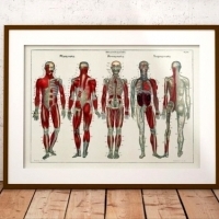
Jak wyglądałoby ludzkie ciało zaprojektowane przez inteligentnego człowieka?
Jak wyglądałoby ludzkie ciało zaprojektowane przez inteligentnego człowieka? Wyeliminuj kolokację narządów rozrodczych i wydalniczych Wyeliminuj martwy punkt siatkówki. Daj ludziom znacznie lepszą kontrolę nad tym, co jest obecnie autonomicznymi funkcjami…

5621AVA. Asta C సెల్యులర్ రీజునేనేషన్. ముఖం కోసం రక్తరసి.
Asta C సెల్యులర్ రీజునేనేషన్. కాటలాగ్ కోడ్ / ఇండెక్స్: 5621AVA. వర్గం: Asta C, కాస్మటిక్స్ చర్య antyoksydacja, యెముక పొలుసు ఊడిపోవడం, ట్రైనింగ్, ఆర్ద్రీకరణ, కాయకల్ప, రంగు యొక్క అభివృద్ధి, సరిచేయడంలో అప్లికేషన్ సీరం కాస్మెటిక్ రకం జెల్ సీరం సామర్ధ్యం…

Te nici są łącznikiem między twoim ciałem fizycznym a twoimi innymi organami.
Eteryczne struny to niewidzialne sznury, które ludzie wiążą z innymi ludźmi przez czakrę serca, na przykład z ojcem, matką, nawet kolegami i ukochaną osobą. Jeśli ktoś uprawia seks z kimkolwiek, sznury te są wiązane z czakrą sakralną. Aby uprawiać seks z…
The Archangels 12 sy ny fifandraisany amin'ny sonia Zodiakà:
The Archangels 12 sy ny fifandraisany amin'ny sonia Zodiakà: Betsaka ny soratra ara-pivavahana sy filozofia ara-panahy maro manome soso-kevitra fa ny drafitra milamina dia mifehy ny fahaterahantsika amin'ny fotoana sy toerana ary amin'ny ray aman-dreny…
FIRBIMATIC. Producent. Maszyny pralnicze.
FIRBIMATIC Polska Sp. z o.o. jest przedstawicielem na Polskę wielu renomowanych producentów maszyn oraz środków chemicznych używanych w pralnictwie. Od początku swojej działalności uruchomiliśmy ponad 150 kompleksowych pralni chemicznych i wodnych. Jako…

ZEGAREK MACARONS BEIGE
ZEGAREK MACARONS BEIGE:Mam do zaoferowania ładny zegarek. Materiał: eko-skóra, metal, szkło Długość paska: ok. 23,5 cm Szerokość paska: ok. 1,9 cm Średnica tarczy zegarka: ok. 3,8 cm Regulacja: tak Zainteresowanych zapraszam do kontaktu.

ಈಜುಡುಗೆ ಎಲ್ಲಿ ಖರೀದಿಸಬೇಕು ಮತ್ತು ಅದರ ಗಾತ್ರವನ್ನು ಹೇಗೆ ಹೊಂದಿಸುವುದು?66
ಈಜುಡುಗೆ ಎಲ್ಲಿ ಖರೀದಿಸಬೇಕು ಮತ್ತು ಅದರ ಗಾತ್ರವನ್ನು ಹೇಗೆ ಹೊಂದಿಸುವುದು? ಸರಿಯಾದ ಉಡುಪನ್ನು ಆರಿಸುವಾಗ, ನೀವು ಅದರ ಕಟ್ ಮತ್ತು ನೋಟಕ್ಕೆ ಮಾತ್ರವಲ್ಲ, ಎಲ್ಲಕ್ಕಿಂತ ಹೆಚ್ಚಾಗಿ ಅದರ ಗಾತ್ರಕ್ಕೂ ಗಮನ ಕೊಡಬೇಕು. ನಮ್ಮ ಆಕೃತಿಯ ಗಾತ್ರಕ್ಕೆ ಸರಿಯಾಗಿ ಹೊಂದಿಸದಿದ್ದರೆ ಅತ್ಯಂತ ಸೊಗಸುಗಾರ ಈಜುಡುಗೆ ಕೂಡ…

szukam męża
szukam męża Jestem osobą wymagającą i dbająca o precyzję i wygląd. Wzrost: 180 cm Wiek: 21 lat oczy: brązowe wykształcenie: wyższe studia matematyczne praca: niezależna finansowo religia: rk szukam astronoma z odpowiednią lunetą może być nawet szalony…

Kapillêre vel: gesigversorging en skoonheidsmiddels vir kapillêre vel.
Kapillêre vel: gesigversorging en skoonheidsmiddels vir kapillêre vel. Kapillêres is geneig om die bloedvate te breek, waardeur hulle rooi word. Effektiewe skoonheidsmiddels vir kapillêres, soos gesigroom of reinigingsskuim, bevat stowwe wat irritasies…

Domovik to miły domowy duch, który mieszka z człowiekiem i pomaga mu w pracach domowych.
Nasi Przodkowie wierzyli w istnienie różnych duchów i wierzyli, że są one najbardziej różnorodne i żyją obok człowieka. Domovik to miły domowy duch, który mieszka z człowiekiem i pomaga mu w pracach domowych. Chroni dom przed kradzieżą, ogniem i złymi…
: Wyróżnione.

Czy ładne kobiety są…

4SEASONS stop half step DIET…

applications needed to earn…

dieta 5 go to the…

dieta 6 go to the sales…

Make Money Online: Passive…

NASA conducts «End Of The…
The Diesel Riddle: The Diesel…
The mystery ceremony of…

The dream of eternal youth is…
Ceremonia Misterium…

Your legs are getting heavy,…
Jc.jd.daaizaza TIAGO I…

…

Make Money Online: Passive…

bKIqf3fh8t0 4SEASONS stop…

: DETALE HANDLOWE: W przypadku…

BIOLOGIA czyli bicie piany:…

Make Money Online: Passive…

Make Money Online: Passive…

Make Money Online: Passive…

MamboJumbo Earn Money Online…

Make Money Online: Passive…

MamboJumbo Earn Money Online…