Nadmi
- Kraj:Polska
- : Język.:deutsch
- : Utworzony.: 06-10-15
- : Ostatnie Logowanie.: 21-07-26


: Opis.: Osąd. Zawsze potępia ten, kto ma mniej energii. Jaki jest cel potępienia? Z reguły celem potępienia jest powstrzymanie działalności czegoś, czego nie lubisz. Na przykład twoje dziecko wkłada brudne palce do buzi lub twój partner nie robi tego, co chcesz. Potępiasz, aby zatrzymać swoje obecne działania i rozpocząć inne - takie, które uważasz za najlepsze lub do zaakceptowania. Ale pomyśl głębiej, dlaczego miałbyś przestać?! Nie dlatego, że dziecko zachoruje lub partner nie zrobi tego, co uważasz za konieczne. Ale dlatego, że wyobrażając sobie dalszy bieg wydarzeń, rozumiesz, że nie masz siły walczyć z tym, co się stanie, i dlatego lepiej jest teraz przestać potępiać. Co więcej, im więcej potępiasz, tym mniej energii ci zostaje. Osądzanie jest procesem, który sam się pozbawia energii. Jak nie potępiać i nie nabierać energii? Po prostu wykonaj odwrotny proces oceniania – podziękuj. Kiedy Twoje dziecko ma zamiar włożyć brudne paluszki do buzi, podziękuj mu za poznanie świata. Kiedy partner nie robi tego, co chcesz, podziękuj mu za inne spojrzenie na świat i otwarcie nowej perspektywy w twoim świecie. DZIĘKUJ ZA ZNACZENIE DZIAŁANIA, a nie za samo działanie, ponieważ działanie może być negatywne, ale znaczenie, dla którego jest wykonywane, jest zawsze pozytywne. Dlatego zadaj sobie pytanie, co chce przez to osiągnąć i podziękuj tej osobie za to. GŁOŚNO. Osoba powinna usłyszeć twoją wdzięczność, wtedy podzieli się z tobą swoją energią. Podziel się życzliwą myślą, zwróceniem uwagi na Ciebie, poprzez nowe działanie. Idea jest więc prosta: potępiasz – tracisz energię, dziękujesz – zyskujesz. Wybierz, co będziesz robić... Znaczenie tego postu nie polega na zabranianiu edukacji i ostrzeganiu dzieci przed niebezpieczeństwem, ale na spojrzeniu na tę akcję z innej perspektywy. Autor - © MarkIfraimov
: Data Publikacji.: 16-07-26
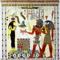
: Opis.: Elektromagnetyczna częstotliwość ultradźwięków emitowana ze szczytu Piramidy Bośni jest mierzona przy 28 kHz. Drgania te są generowane od punktu początkowego poniżej Piramidy Słońca na głębokości 2440 metrów. „Badania Bośniackiej Piramidy Słońca przeprowadzone przez dr Oldfielda wykazały, że pola elektromagnetyczne generowane nad piramidami mają bardziej pionową orientację, co uważa się za niezwykły fakt, ponieważ wzorce elektromagnetyczne występujące nad formacjami takimi jak naturalne wzgórza i góry, zwykle mają orientację poziomą. Jony ujemne i właściwości lecznicze są poza schematami w bośniackich piramidach. Różne pomiary wykonane w podziemnym labiryncie tuneli wykazały ogromne stężenie jonów ujemnych (atomów lub cząsteczek, które mają więcej elektronów niż protonów w jądrze) zaskakująco sięgające poziomy do 40 000 jonów na centymetr sześcienny, znajdujące się w odległości 200 metrów od wewnątrz. Piramida jest wzmocnionym odbiornikiem lub rezonatorem najróżniejszych rodzajów pól energetycznych, czyli fal elektromagnetycznych, promieni kosmicznych, wyładowań elektrycznych, fal grawitacyjnych, itp., otaczających naszą planetę i znajdujących się w powietrzu wokół i wewnątrz piramidy.
: Data Publikacji.: 16-07-26
: Opis.: Jeśli ktoś ci zazdrościł, mówi jeden z chińskich mędrców, to na subtelnej płaszczyźnie odebrał ci energię, ale możesz ją odzyskać. Nie wymaga to żadnych specjalnych rytuałów ani działań. Wszystko we wszechświecie opiera się na intencji. Musisz tylko stanowczo powiedzieć głośno lub napisać na papierze, że chcesz odzyskać całą energię, którą zabrali Ci zazdrośni ludzie i skierować ją na własny rozwój. I to wszystko. Nie proś o karanie zazdrosnych ludzi, to nie twoja sprawa, nie musisz wyobrażać sobie ich twarzy i mentalnie szturchać palcem. Najbardziej znani zazdrośni ludzie teoretycznie mogą nawet nie być ci znani. Po prostu powiedz słowa i obserwuj wynik. Zwykle trudne do rozwiązania problemy rozwiązuje się w absolutnie niewiarygodny sposób, wszystko dobrze się układa, pojawiają się opłacalne oferty. Oczywiście ta sama zasada działa w odwrotną stronę. Dlatego nie zazdrość, abyś kiedyś nie znalazł się w sytuacji, w której część energii odpłynie do kogoś, kto Twoim zdaniem ma we wszystkim szczęście. To proste ćwiczenie, wykonane kilka razy, w niesamowity sposób odmieni Twoje życie. Właściwy Apel: „Oddaję całą energię, którą zazdrośni ludzie odebrali mi od momentu moich narodzin do dnia dzisiejszego, i kieruję ją na własny rozwój”. Obraz: pinterest #marinaczajkowska
: Data Publikacji.: 16-07-26
: Opis.: Koncentracja naszej uwagi ma potężną siłę! Jeśli nieustannie skupiasz swoją uwagę na problemach, potrzebach i kłopotach, z czasem w Twoim życiu utworzy się uporczywe pole negatywnej energii, tworzące błędne koło z blokady problemów, konfliktów i braku energii życiowej... Jeśli przeciwnie , nawet pomimo pewnych problemów i kłopotów skupiasz swoją uwagę na ich rozwiązywaniu, a jednocześnie na wszelkich pozytywnych drobiazgach i okolicznościach, w Twoim życiu tworzy się kreatywne pole energii, potężny magnes przyciągający szczęście, pozytywne wydarzenia i witalność ... A cała tajemnica tkwi nie tyle w negatywnym/pozytywnym myśleniu, co w potężnych wibracjach energii, które ono tworzy… i które z kolei tworzą naszą rzeczywistość. Trzeba pamiętać o najważniejszej rzeczy: Twoje Życie i Energia zawsze zmierzają w kierunku Twojej najsilniejszej myśli.
: Data Publikacji.: 15-07-26
© Web Powered by Open Classifieds 2009 - 2026